Monday, June 30, 2008

A Change in Thinking

This post serves more as a notification: 
After 3 weeks of thinking like an engineer, and an amazing weekend surrounded by the arts and culture of Kyoto, I have decided that it was time to switch my thinking to that of a designer.  I think the answers will be unexpected for the Japanese Engineering professors, but I hope to entertain new ideas amidst a world of rational.

Enjoy!

Wednesday, June 25, 2008

Communication Technology in ITS

Latest Advanced Technology and Tasks in Automobile Engineering

Seminar 7: Communication Technology in ITS

Jenna M. Eason, North Carolina State University


1) Short Range Communication will be widely used in ITS

            a) What are the merits and demerits of short range communication?

DSRC, Dedicated Short Range Communication, is effective in ITS such as electronic toll collection.  It provides less delay and is faster than long range technology because two units send signals, which means the distance and time each signal must travel is cut in half.  DSRC also provides for more privacy and security. Since the signal is limited, it is much less likely that another receiver will be able to get your information.  This technology also allows for frequent use.  DSRC has a limited bandwidth, which could be good or bad.  The limited bandwidth provides additional security so that other receivers are not contacted, but it may be more difficult to locate the correct receiver.  The signal must be standardized because of this.

            b) Why does ITS use short range communication?

The above merits justify ITS’s use of short range communication.  These systems are used in (or proposed to be used in) Electronic Toll Collection (ETC), information delivery, to receive traffic information, for electronic payment at the gas station, and for parking access management.  Currently, over 20 million units are used in Japan.


2) Travel time prediction is one of the key applications for ITS

            a) Describe characteristics of travel time, which enable travel time prediction

Travel time varies according to the change of traffic conditions after departure.  Travel time can be predicted if certain factors are taken into account throughout the journey.  Historical data fused with current conditions can help with an accurate prediction.  Historical data includes VICS, weather information, and probe information.  It is also important to keep in mind that historical data constantly changes with current conditions and there must be an accurate way to process this information.  Through a complex matrix complication, prediction accuracy is improved.  Also, predicted information can be received through real time data from the internet, mobile phone or car navigation system.  Currently, reviewing real-time data, historical data, the fusion of data, and Mitsubishi’s new prediction formulation, results in 4 very different solutions.

            b) Write your ideas about how to model the above characteristics

This is a completely unfamiliar area of research to me and I am excited about the advanced accuracy of combining historical data with real-time information.  I think it would also be interesting to fuse demographic information about the driver and their trends into the matrix.  This information could predict the driving style and speed of a typical 25-year-old female and compare this with a typical 57-year-old male.  The system should also take into account the driver’s personal driving style.  Are they a speeder, just-the-limit, or grandma style?


Sources

(1) Kumazawa, Hiroyuki, Mitsubishi Electric Corporation, Advanced Technology R&D Center, “Communication Technologies in ITS”, Latest Advanced Technology and Tasks in Automobile Engineering course at Nagoya University, June 23, 2008.

Crash Safety

Latest Advanced Technology and Tasks in Automobile Engineering

Seminar 6: Crash Safety

Jenna M. Eason


The full frontal ridge barrier test of a car (mass m) with an initial velocity of V0 was modeled by a simple spring-mass model.  The stiffness of the car during loading is assumed to be k.  Assuming that there was no rebound, calculate the car acceleration, velocity, and displacement as a function of time t; and draw a schematic graph of the acceleration, velocity, and displacement as a function of time.


 (I could not post the context of this report because of errors within the HTML against the mathematical equations)

Sunday, June 22, 2008

Automotive Embedded Computer Systems

Latest Advanced Technology and Tasks in Automobile Engineering

Seminar 4: Automotive Embedded Computing Systems

Jenna M. Eason


Investigate on one of the following systems/services and write a short paper on its purpose, function, and system structure.

I have chosen “immobiliser”.

An immobilizer is an electronic device fitted to an automobile, which prevents the engine from running unless the correct key, code, or token is present [1].  The primary purpose of this device to prevent theft and “hotwiring” of a vehicle.   This is achieved due to a tiny transponder most often embedded into the vehicles ignition key, which controls the immobilizer system.  The transponder contains a unique and unalterable identification code that corresponds to that particular vehicle.  Every time the key is inserted into the ignition, a radio frequency reader located in the steering column is triggered. As the ignition is turned, the reader is activated and sends out a wireless signal (unique binary code) to the transponder.  The signal powers up the transponder’s capacitor, allowing it to transmit its unique code back to the reader.  The reader is comprised of a very small antenna integrated with the ignition switch and the steering lock cylinder, and a transceiver, which is connected to a control module in the engine’s central computer.  The computer controls vital automotive functions, such as the ignition and fuel supply circuits [2].  The control module then compares this signal to the code stored in its memory.  If the two codes match, and the appropriate additional security challenges are passed, the control module enables the engine’s computer or the fuel pump relays.  If the codes do not match, an alarm indicator will show and the engine will not start [2]. To disarm the system, a special transponder key or code is required.  These systems arm automatically once a vehicle shuts down (called passive arming) [3].

One 1999 study reports that auto theft rates in Western Europe dropped by over 1/3 from a peak of 144,000 in 1993 to 95,349 in 1997 [2].  It is believed that this drastic decrease is the direct result of the introduction of Automotive Immobilizer Anti-Theft Systems in 1993.  Upon its introduction to the European market, the system became mandatory equipment on all new vehicles sold beginning in 1995 [2].

Following this success, factory and aftermarket immobilizer systems are now featured on many models sold throughout countries outside of Europe.  The companies employing this technology include Chrysler, Ford, Hyundai, and Toyota.  Aftermarket sales have also proved highly successful [2].   

Sources:

1. www.Wikipedia.com

2. http://www.theautochannel.com/news/press/date/19990601/press024256.html

3. http://www.absoluteautoguard.com/index2.php?option=com_content&do_pdf=1&id=4  

Monday, June 16, 2008

Safety Engineering

Latest Advanced Technology and Tasks in Automobile Engineering

Seminar 5: Safety Engineering for Prevention of Accidents

Jenna M. Eason


Summarize information from today’s Lecture.

Safety engineering focuses on three categories of errors, which lead to accidents: Control Technology, Sensing Technology, and Human Science.  Human error is the cause of 80% of accidents and is the result of the perception, decision, and motion process.  The remaining 20% are caused by system failures.  The goal is to analyze human factors and create an assist system to help the driver and to create an infallible and redundant control system.

First, human behavior must be analyzed.  To do this, complex motions are decomposed into primitive motions and mode transitions between them in a scientific mode and graphing system.  Complex mathematical systems are able to quantify and classify human behavior and reactions.  This information can be graphed, which allows visual analysis.  From this information, assisting systems can be developed.  These systems may be also quantified, visualized, and analyzed for effectiveness.

Nissan employs this technology in developing a system, which responds to the “six level shield”.  Each level of the shield represents a varying level of risk from normal driving to an unavoidable contact zone.  Using sensor technology, as a vehicle approaches an obstacle, it responds at a different level based on which level of the shield the object is in.  For example, it may create visual and audio warning signals, release the gas, or even press the break, to avoid an accident.  This technology aims to decrease the number of serious and fatal injuries by making the driver more aware, and assisting them in a difficult situation.

Several of these systems are in the development process.  One such system is referred to as “fault tolerant control of lateral motion”.  This system operates with sensors, which detect the distance between two cars.  One goal is to maintain a constant range of a safe distance from the car in from.  The other goal is to detect deviations from the center of the road to ensure that the car is staying within the proper lane.  These systems were tested through simulations and an experimental site for accuracy and proved effective.  This technology will be available in September for US Nissans. 


Sources:

1) Akatsu, Yousuke, Nissan Motor Co. LTD, “Innovative Safety Concept and Solution”, presentation for Latest Advanced Technology and Tasks in Automobile Engineering course at Nagoya University, June 16, 2008.

2) Suzuki, Tatsuya, Nagoya University Dept. Of Mechanical Science and Engineering, “Safety Engineering for the Prevention of Accidents”, presentation for Latest Advanced Technology and Tasks in Automobile Engineering course at Nagoya University, June 16, 2008.

Friday, June 13, 2008

Car Materials and Its Processing

Latest Advanced Technology and Tasks in Automobile Engineering

Seminar 3: Car Materials and its Processing

Jenna M. Eason


Choose the impressive metal forming process or materials in the lecture and describe it in detail.

Carbon fiber is the current ideal material for many automotive components.  Carbon fiber is extremely strong because of microscopic bonding of carbon atoms.  The fibers that make up a strand of carbon fiber are extremely thin (0.005-0.010 mm in diameter) and are aligned along a relatively parallel axis [1].  Twisting these fibers results in a yarn that is incredibly strong, small, and lightweight.  Theses yarns may be processed into materials in the same processes as most other textile yarns.  Weaving and 3D Weaving are becoming the most common means of manufacture.

Carbon fiber can be combined with a plastic resin and wound or molded to form composite materials such as carbon fiber reinforced plastic (CFRP).  This is the technology briefly discussed in Wednesday’s lecture.  This provides for a very high strength-to-weight ratio material.  The density of carbon fiber is also considerably lower than the density of steel, making it ideal for applications requiring low weight (such as automotive).  The properties of carbon fiber such as high tensile strength, low weight, and low thermal expansion make it a very ideal choice for transportation vehicles. [1] The downside to this technology is very high costs, which results in low usage for production vehicles. 

 Carbon fiber reinforced plastic is used extensively in high-end automobile racing.  The high cost of carbon fiber is mitigated by the material’s unsurpassed strength-to-weight ratio, and low weight is essential for high-performance automobile racing.  Racecar manufacturers have also developed methods to give carbon fiber pieces strength in a certain direction, making it strong in a load-bearing direction, but weak in directions where little or no load would be placed on the member.  Conversely, manufacturers developed omnidirectional carbon fiber weaves that apply strength in all directions [1].  Much of this research is being conducted at my home college: the North Carolina State University College of Textiles.

Currently, CFRP are being used in aerospace applications, sailboats, lightweight bicycles and motorcycles.  They are also used in many non-transportation good including fishing rods, computers, and guitar strings.   All at a high price tag.  Much research is being conducted to lower the costs of carbon fiber composites by combining recycled materials to the raw resources, but there is still much to be discovered so that this technology can be widely applied in order to lower emissions and improve performance.


Sources

(1) www.Wikipedia.com  

Monday, June 9, 2008

Evaluating Driver's Behavior

Latest Advanced Technology and Tasks in Automobile Engineering

Seminar 2: Observation and Evaluation of Driver’s Behavior

Jenna M. Eason


1. Look and touch the sensor car.  Observe what kind of sensors attached.  What sensors do you think yet need and why?

I believe there is a possibility of a device that can observe facial expressions and quantify this data.  For example, a static picture of the driver’s face can be taken in a relaxed environment.  Video will then record deviations in expression, notably in the eyes, 

brow, mouth, and possibly clenching of the teeth.  As a driver gets excited, upset, or drowsy, these expressions will be detected and analyzed.  For example, the level and angle the brow raises or droops is proportional to the level of the driver’s excitement.  Of course this data will vary greatly with different drivers, but the delta is what will be plotted.

Another sensor could record brain activity and map this data.  This information shows excitement vs. lack of activity and is a more direct measurement the physical actions.

A final sensor could detect the amount of pressure of the driver’s back against the seat.  If the driver is excited they may lean forward to see the road better and grip the steering wheel more tightly (another possible sensor) or press against the back if they are slamming the breaks.  This data is to be visualized next to normal.

A final thought is another option for test conditions.  The driver should be tested when eating and smoking to detect how these actions affect driving ability.

2. Plot a car trajectory of taking over.  Describe which part of the trajectory representing the driver’s characteristics and how.

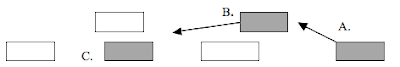
A. Driver is calm, releasing pressure on the gas as he prepares to predict passing the vehicle in front.

B. Driver leans forward and begins to excite when he sees car in passing lane that was not visible from A.  Driver must accelerate.

C. Driver is very excited, palms are sweating, talking has completely ceased as he tries to maneuver between cars.  At the end of C driver has to break unexpectedly because of front car and is very excited.

Driver decides not to pass anymore after this excitement.  He is a very bad driver for trying to make this pass.

3. What do you think is a good measure to detect drowsiness?

Facial expressions are key to detecting drowsiness.  The same device described in Question 1 will work well.  Signals for drowsiness include droopy or blinking eyes, yawning, fidgeting, head dropping, and body position.  The control over the vehicle will decrease and the vehicle will start to swerve.  This motion can be recorded and if repetitive can signal an alert.   Also, often when drowsy, the driver will unintentionally “tailgate” the vehicle in front.  This can be recorded with the radar detection already placed on the front of the vehicle.  If there is mapping for the brain, a wandering mind is a sign of drowsiness

4. Describe overall impression of the class.

I thoroughly enjoyed this seminar and am very interested in detecting driver behavior and emotional response to improve the driving experience.  

What is the ideal car of the near future?

Latest Advanced Technology and Tasks in Automobile Engineering

Seminar 1: The Car Industry, Market Trend, Circumstance, and its Future

Jenna M. Eason


What is the ideal car of the near future?

The Eco-Glider is a luxury crossover vehicle, which appeals to the sustainable-minded young professionals of Generation Y.  This demographic is the most physically active, technology-dependent, and social group seen yet.  They have also been labeled the most educated generation in history, which results in the highest incomes to date.  With adventure and technology at the forefront of Gen Y’s desire to learn, this group hosts the biggest supporters of the Green Trend.  All these factors are taken into consideration when evaluating Generation Y’s buying habits in order to develop the Eco-Glider.

Similar to the technology employed in creating the Hyundai QarmaQ concept, 95% of the Eco-Glider’s exterior materials are developed from PET plastic bottles.  This technology recycles around 1000 bottles per vehicle but also results in a weight reduction of up to 60 kg and offers an average fuel savings of up to 80 liters/year.  Since this vehicle is lighter and constructed from a more flexible material, pedestrian safety is increased and the ability to create complex 3D shapes is improved.  The final result is a shell that is 100% recyclable and requires less energy to produce than the carbon fiber competitor. 

The cabin of the Eco-Glider comfortably hosts space for 5 passengers and enough technology to keep the active minds of Generation Y occupied on their 45-60 min daily commutes.  The vehicle can be programmed to near-full computer operation and voice command.  The central computer will control cruise speeds, obstacle avoidance, and adjust to environmental conditions.  Hundreds of mini computers will include GPS, Internet, phone, TV, surround sound, and voice-record reminder messages.  Cameras placed throughout the vehicle allow for 360-degree visibility inside and out.  The windshield wiper activation and speed is automatically adjusted through sensor monitoring.  The interior climate control system operates a near-silent AC and heating system, as well as seat warmers and coolers.  One of the most innovative features of the Eco-Glider is the ability to recognize when the owner is approaching the vehicle, which unlocks the driver-side door.  Once inside, the vehicle adjusts to memory of the driver’s preferences of all the above features.

The Eco-Glider is notable for its powerful performance and is safe at high speeds.  The vehicle is Generation Y’s ideal choice for a comfortable daily commute, but is also the top choice all-terrain vehicle for adventurous weekend enjoyment.  Another unique feature is Eco-Glider’s ability to automatically adjust interior and exterior lighting, steering, suspension, and drive (on- and off-road use) to respond to the environment.

The vehicle reduces carbon dioxide emissions by combining hybrid technology and using biofuels (similar the the Saab BioPower Hybrid Concept).  By the year of Eco-Glider’s introduction, biofuels will be available throughout most countries.  For the areas where bio-fuel is not a readily available option, a direct injection system designed to burn 100% ethanol or any mixture of ethanol and petrol.  Ethanol has a higher octane rating but packs less energy per gallon of gasoline; therefore Eco-Glider uses turbo charging to give the engine more power, without risk of “knocking”.  Performance is also enhanced via extra boost from the electric motors.  Another unique feature is the “zero-mode” button that gives the ability to drive all-electric at speeds lower than 20 mph (useful for sitting in traffic).

Sources: www.hybridcars.com, www.autoblog.com, www.wikipedia.com